End to End Digital TV
May 20, 2022
TV over Fiber
TV has historically been an analog service delivered over radio frequency “RF”. Old TVs has controls to tune the receiver to a channel just like a car radio. TV is almost entirely digital now, but it still uses the same kind of RF transport like it used to. Ziply uses a video design called RF over Glass or RFoG, which works to convert the RF TV signals to a light signal on fiber (glass).
The journey from the TV station to a Ziply customer’s home is complex but elegant. It all starts at the TV broadcasting station. Incidentally, I’ve been to KOIN’s TV station at Sylvan, so I can share a little about how that works too.
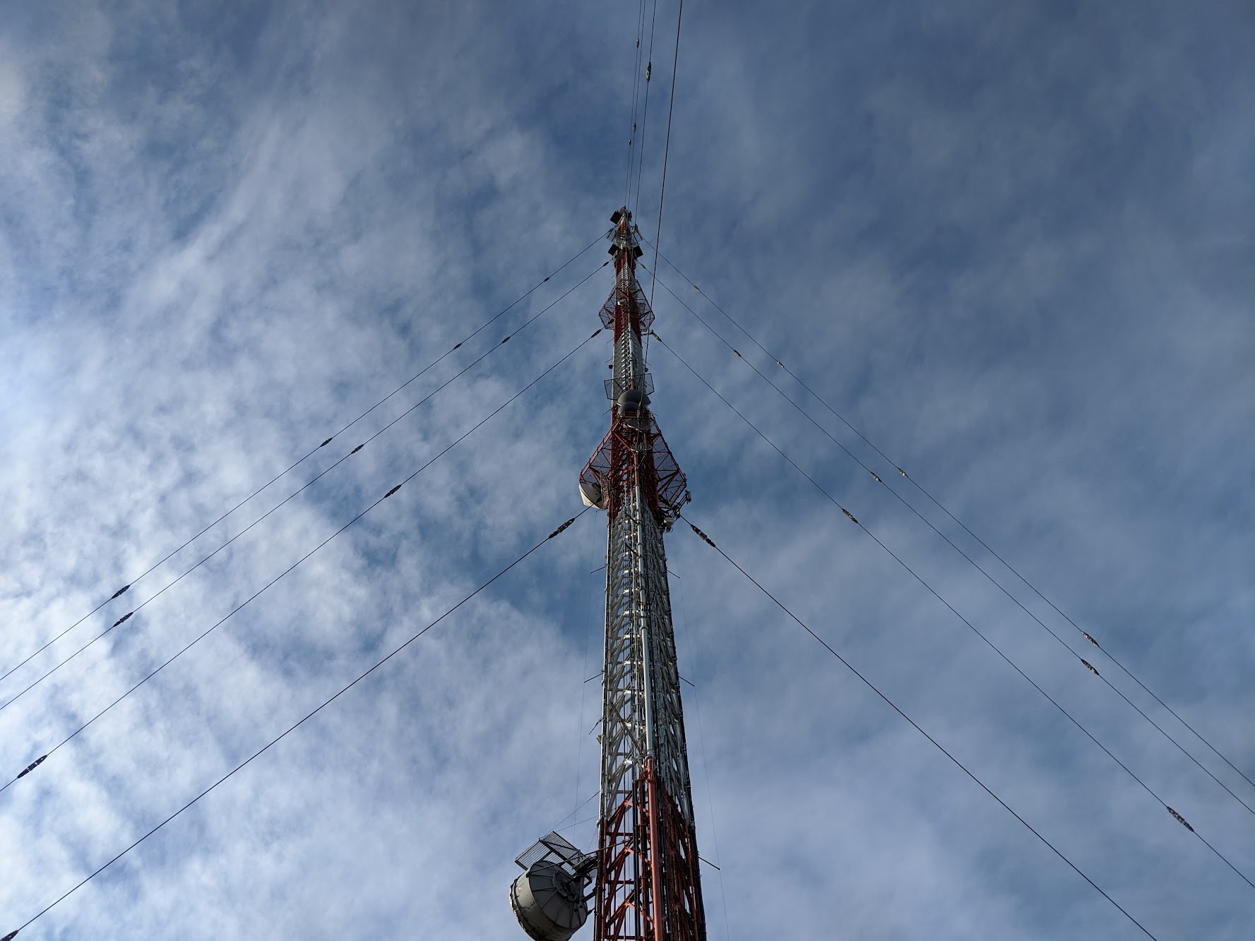
The TV signal is broadcast from their studio or field units (video trucks or helicopters) to a receiving antenna aboard a satellite or on this tower. Satellite transmissions work well in places that don’t have a direct line of sight to the tower, but incurs additional latency and can’t be quickly repositioned because, well, it’s a satellite in space. The TV signal travels down cables inside the tower and into a concrete building below where it’s demodulated and sent out for distribution. Ziply picks up these signals wirelessly with antennas at video offices which are then transmitted over coax cable to the video headend – a row of racks that convert digital TV signals into a wavelength of light that’s sent to customers over fiber. Let’s take a closer look at the video headend in Gresham. Most of the video headend in Gresham
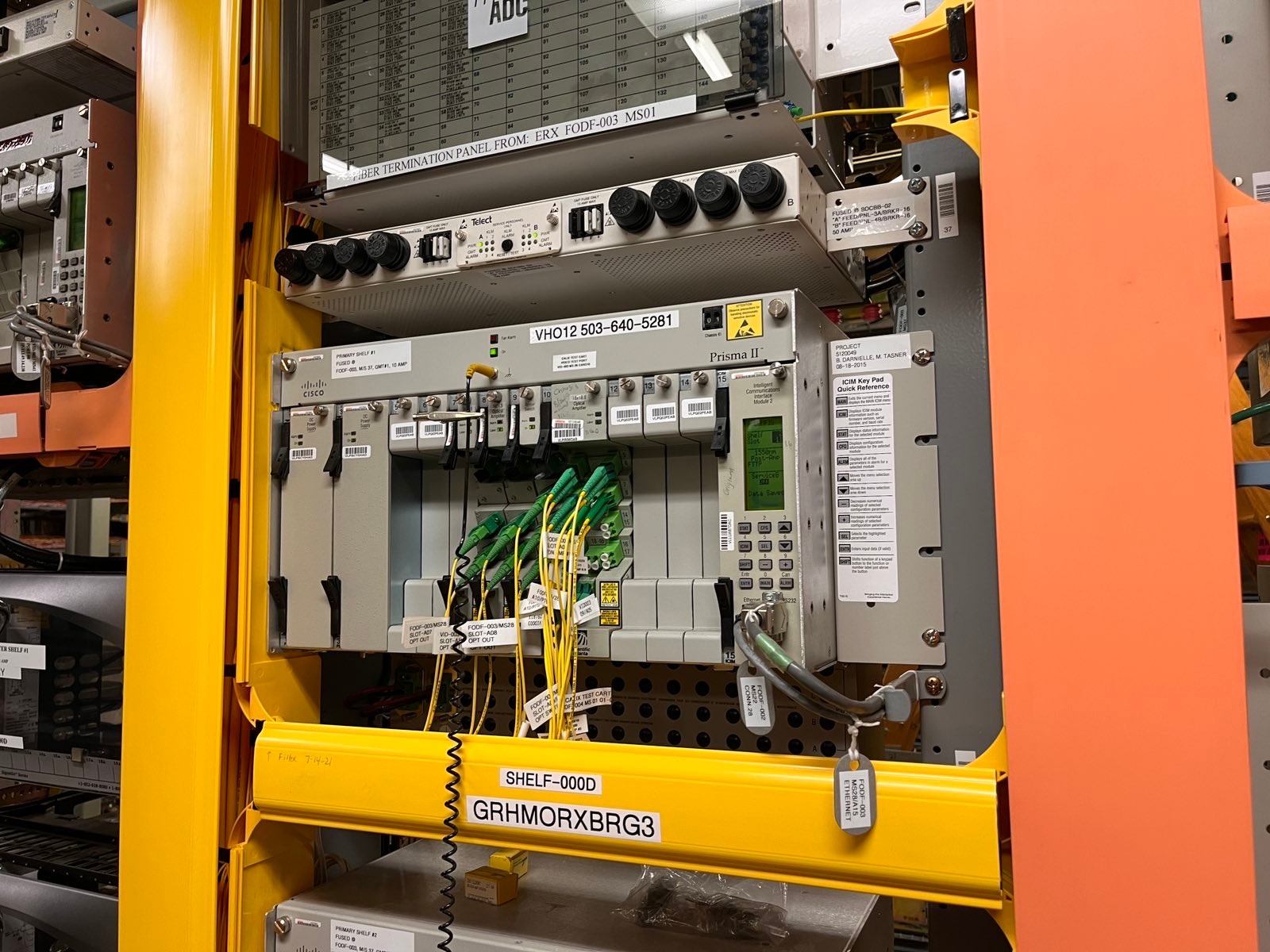
TV signals arrive at the video headend to a broadband media router (BMR) at the bottom left of the left picture above. The BMR demodulates these coax video signals and converts them into light that can be sent over fiber.

BMR in Gresham
Digital TV signals travel through small yellow fibers out of the BMR into a series of EDFAs (Erbium-Doped Fiber Amplifiers). EDFAs are super cool: they amplify a wavelength of light so it’s bright enough to travel long distances to the customers’ buildings. Fiber is essentially made of sand – it’s purified silica that’s turned into a very thin strand of glass to act as an optical waveguide to direct light inside the cable. Fiber can contain many wavelengths concurrently, EDFAs can inject their own optical energy into the fiber to amplify the original wavelength on the input. A pump laser inside the EDFA generates a precise wavelength of light of lower frequency than the optical signal being amplified, which is shot into a piece of Erbium-doped fiber. Erbium ions in the fiber absorb pump laser photons, which push the original photons along through a process known as “population inversion” within the Erbium-doped fiber section.
EDFA amps
If you’ve been paying especially close attention to fiber connectors on this blog, you may have noticed there are different colors of both cable and connector. This isn’t an accident! Blue connectors are known as Ultra Physical Contact (UPC) while green ones are Angled Physical Contact (APC). The end of APC connectors are polished at an angle, while UPC connectors are almost flat with very slight rounded edges. The difference is that with UPC connectors, reflected light at the connector bounces directly backwards into the light source, rather than diagonally into the outer cladding of the cable like in APC connectors. Reflectance can be a big problem in optical networks, especially with higher wavelengths like 1550nm that’s used in video applications like this headend.
EDFA racks in the video headend
Now that the signal has been converted from coax to fiber in the BMR and amplified at EDFAs preamps, it’s sent over APC fiber (note the green connectors) into another EDFA to further amplify the signal. The output of the EDFAs travel in overhead cable runs to the frame where they land on distribution panels.
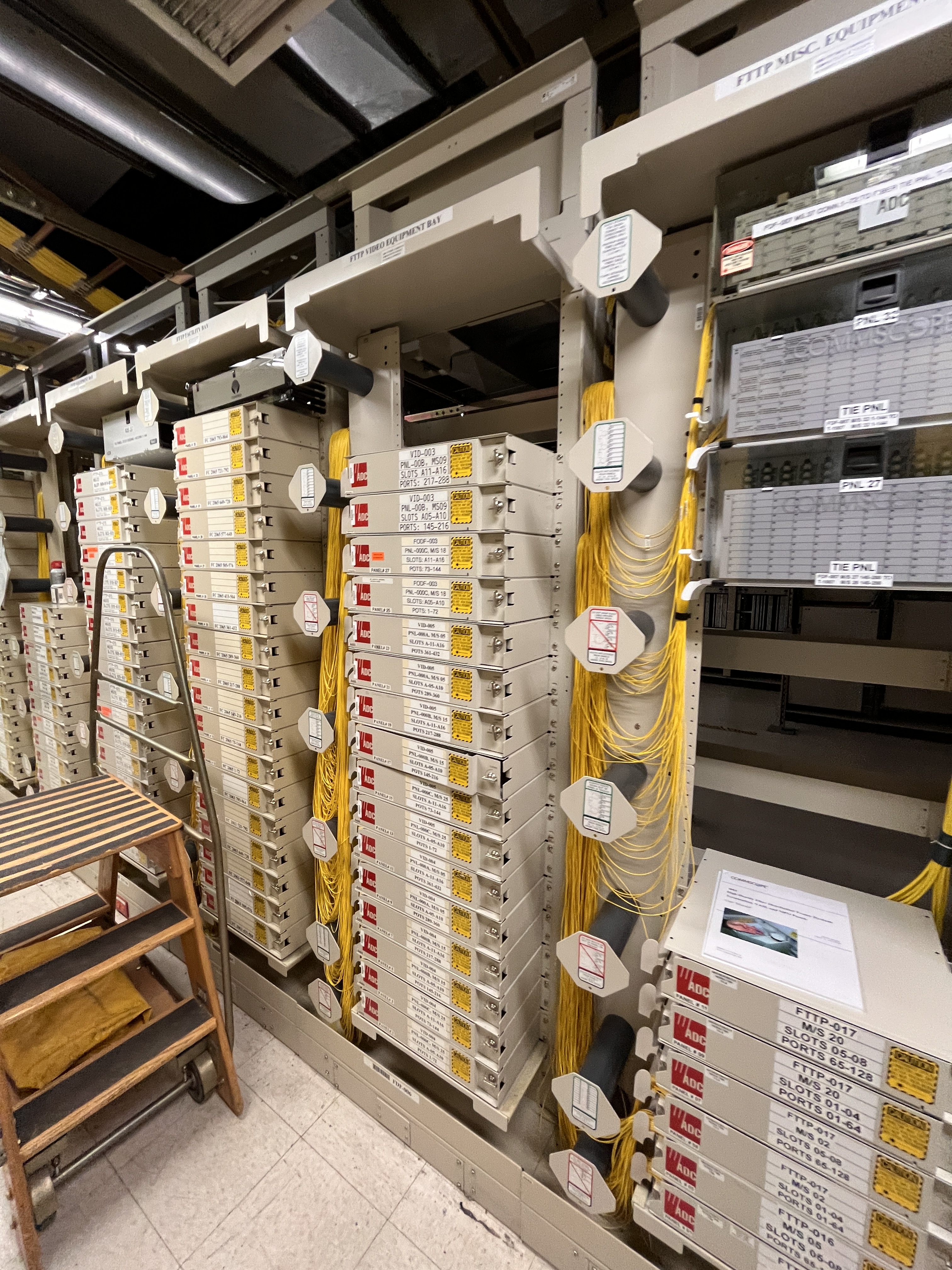
Fiber distribution panels
These are the same distribution panels that I showed in the last post. On one side, they go out to the OSP (OutSide Plant) cables underground to customers’ buildings, and on the other they go into fiber multiplexers (muxes).
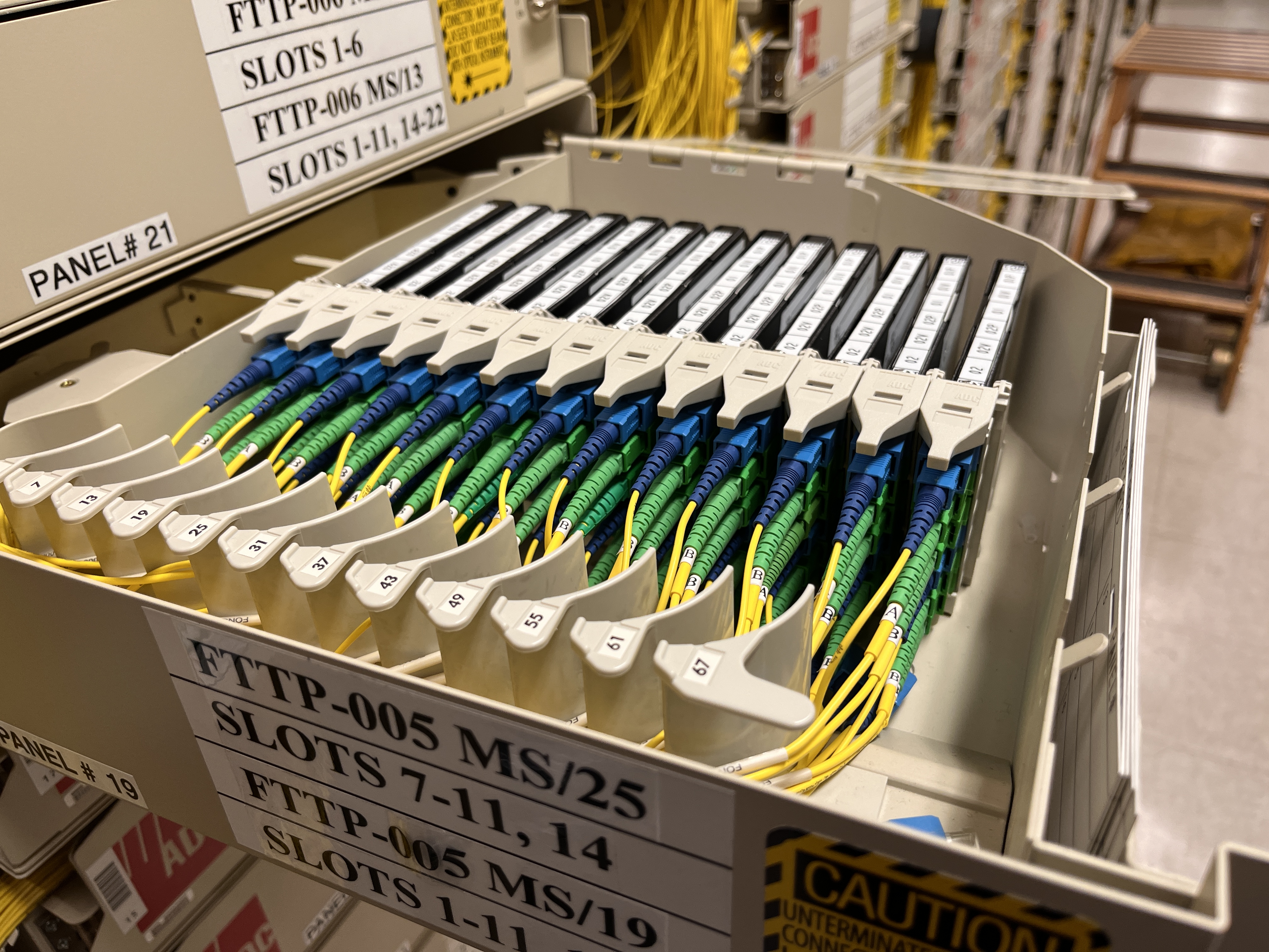
Mux cassettes
Each cassette has two independent muxes stacked on top of each other. The top UPC cable goes to the OLT for Internet as discussed in my week 1 post, the lower cable comes from the EDFA racks in the video headend, and the lowest APC cable goes out to the street to customers.
Not every fiber customer has a dedicated fiber strand back to a central office. Most share it 32 ways with the help of one of these cabinets:
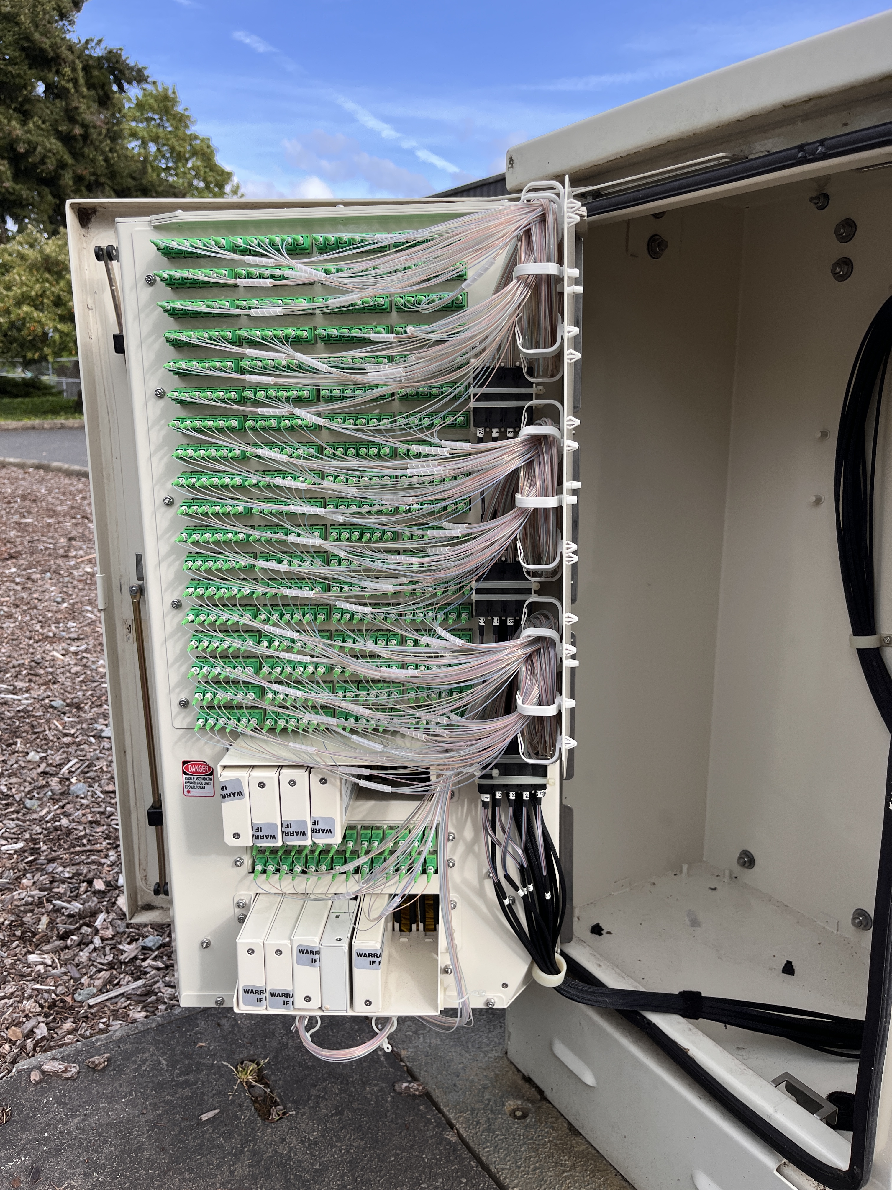
Splitter cabinet
These distribution cabinets have 2 big cables going into them. F1 cable goes back to a central office where it connects to the distribution panels and muxes, and F2 cable going to individual customer buildings. The top rows of APC in this picture are F2 breakouts, and the 2 smaller rows below are the F1 breakouts. The metal cartridges are Planar Waveguide Circuit (PLC) splitters which evenly splits an optical signal to and from multiple fibers. For Ziply, each PLC splitter connects 32 houses to a single port on the mux. If you’re really fancy, you can get a MetroE circuit that doesn’t have a PLC splitter at all. Instead, it comes over dedicated fiber for speeds of 10G or more!